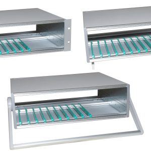
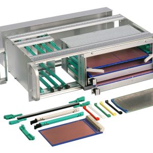
KM6-II Subracks
Fully compatible with DIN 41494 part 5 and IEC 60297-3, KM6-II subracks are strong, versatile and easy to assemble making them well suited to light and medium duty applications. The tiebars are of large section for rigidity and are secured using two fixing screws into counterbored holes. The screws therefore act as locating dowels promoting a high degree of accuracy during construction. The range is extensive, offering 3U, 4U, 6U, 7U and 9U heights in width of 24, 42, 60 & 84HP and depths of 160, 240, 300, 360 & 420mm. KM6-II Subracks are supplied either in kit form or individual component parts and are complimented by a wide range of accessories, including EMC conversion kits, guides, front panels and plug-in modules.
Download CatalogueKM6-II Subrack, Backplane Mounting
| Height | Depth (mm) | Width (HP) | Order Code (Without Handles) | Order Code (With Handles) |
|---|---|---|---|---|
| 3U | 180 | 42 | 950-202583 | |
| 180 | 82 | 950-202581 | 950-232564 | |
| 240 | 42 | 950-202592 | ||
| 240 | 84 | 950-202589 | 950-232565 | |
| 300 | 84 | 950-223550 | 950-232566 | |
| 360 | 84 | 950-202594 | 950-232567 | |
| 6U | 180 | 42 | 950-202584 | |
| 180 | 84 | 950-202582 | 950-232604 | |
| 240 | 42 | 950-202593 | ||
| 240 | 84 | 950-202590 | 950-232599 | |
| 300 | 84 | 950-223551 | 950-232601 | |
| 360 | 84 | 950-202595 | 950-232602 | |
| 420 | 84 | 950-202597 | 950-232603 | |
| 9U | 240 | 84 | 950-202591 | |
| 300 | 84 | 950-224198 | ||
| 360 | 84 | 950-202596 | ||
| 420 | 84 | 950-202598 |
KM6-II Subrack, DIN 41612 Connector Mounting
| Height | Depth (mm) | Width (HP) | Order Code (Without Handles) | Order Code (With Handles) |
|---|---|---|---|---|
| 3U | 240 | 84 | 950-232054 | 950-232570 |
| 360 | 84 | 950-232055 | 950-232571 | |
| 6U | 240 | 84 | 950-232056 | 950-232609 |
| 360 | 84 | 950-232057 | 950-232610 |
KM6-II EMC Conversion Kits
KM6-II subracks can be retrospectively EMC screened or closed by the addition of covers and a suitable front and rear panel. Two Basic types of screening cover are available:
OVERALL, which provide a screen over both the card area and the rear connector/backplane area. In this version, the rear of the subrack is completed by the addition of conventionally fixed panels, either full width or in combinations of lesser width front panels.
PCB AREA ONLY, this application requires a motherboard/backplane which is specifically designed to provide rear screening using ground plane technology. With this geometry, only the front aperture requires screening panels.
KM6-II EMC Conversion - Overall Depth
This kit contains the parts required to convert an 84HP subrack for EMC.
Notes:
1. EMC front and rear panels and EMC fingers should be ordered separately to suit requirements.
2. 42HP and 84HP card frames can be effectively screened by ordering individual covers and rear closing angles together with the EMC finger strip detailed below.
| Height | Ventilated | PCB Depth (mm) | End Plate (mm) | Order Code |
|---|---|---|---|---|
| 3U | No | 160 | 240 | 950-240574 |
| Yes | 160 | 240 | 950-240575 | |
| 6U | No | 160 | 240 | 950-240576 |
| Yes | 160 | 240 | 950-240577 | |
| 9U | No | 160 | 240 | 950-240578 |
| Yes | 160 | 240 | 950-240579 | |
| 3U | No | 160/220 | 300 | 950-240580 |
| Yes | 160/220 | 300 | 950-240581 | |
| 6U | No | 160/220 | 300 | 950-240582 |
| Yes | 160/220 | 300 | 950-240583 | |
| 3U | No | 160/220 | 360 | 950-240584 |
| Yes | 160/220 | 360 | 950-240585 | |
| 6U | No | 160/220 | 360 | 950-240587 |
| Yes | 160/220 | 360 | 950-240588 | |
| 9U | No | 160/220 | 360 | 950-240589 |
| Yes | 160/220 | 360 | 950-240590 | |
| 6U | No | 160/220/280/340 | 420 | 950-240562 |
| Yes | 160/220/280/340 | 420 | 950-240563 | |
| 9U | No | 160/220/280/340 | 420 | 950-240564 |
| Yes | 160/220/280/340 | 420 | 950-240565 |
FI Finger Strip
Supplied in lengths of 381mm consisting of 60 fingers. The fingers are self adhesive for easy application and replacement in the field. The quantity of fingers fitted at any panel/subrack interface is selected according to the performance required from the overall screen. Please see page 12 for details. They can be cut using a sharp pair of scissors, taking care to avoid crushing during cutting.
RFI finger strip material: Beryllium copper
| Description | Length | Order Code |
|---|---|---|
| RFI Finger strip | 381mm (60 Fingers) | 930-238243 |
KM6-II EMC Conversion: Top and Base Covers – Overall Depth
The ‘Overall’ EMC conversion kits are also available in their constituent parts.
In addition to the 84HP versions, a small range of ventilated overall covers is available in 42HP and 60HP widths. In order to fit these, it is necessary to order reduced width front extrusions and tapped strips, M4 fixing screws and rear closing angles.
| Width | Ventilated | PCB Depth (mm) | End Plate (mm) | Order Code |
|---|---|---|---|---|
| 42HP | No | 160 | 240 | |
| Yes | 160 | 240 | 950-259417 | |
| 60HP | No | 160 | 240 | |
| Yes | 160 | 240 | 950-259418 | |
| 84HP | No | 160 | 240 | 950-240557 |
| Yes | 160 | 240 | 950-240553 | |
| 42HP | No | 160/220 | 300 | |
| Yes | 160/220 | 300 | 950-259419 | |
| 84HP | No | 160/220 | 300 | 950-240556 |
| Yes | 160/220 | 300 | 950-240552 | |
| No | 160/220 | 360 | 950-240559 | |
| Yes | 160/220 | 360 | 950-240554 | |
| No | 160/220 | 420 | 950-240558 | |
| Yes | 160/220 | 420 | 950-240555 |
Rear Closing Angles
These are fitted at the rear in conjunction with rear mounting tie bars. EMC Beryllium copper fingers should be ordered separately to maintain the shield between the subrack and EMC panels.
| Description | Order Code |
|---|---|
| 3U Rear Closing Angles | 950-240549 |
| 4U Rear Closing Angles | 950-259278 |
| 6U Rear Closing Angles | 950-240550 |
| 7U Rear Closing Angles | 950-259279 |
| 9U Rear Closing Angles | 950-240551 |
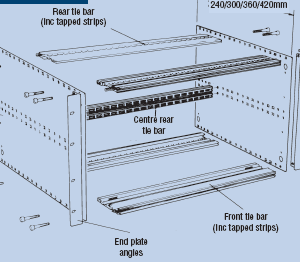
Rear Mounting Tie Bars
Two should be ordered per subrack. 84HP version use a plain tie bar. Other widths use standard front tie bars. Sold in singles. Two tapped strips and eight fixings are also required.
| Width | Type | Order Code |
|---|---|---|
| 84HP | Plain Tiebar | 950-221909 |
| Tapped Strip | 950-202001 | |
| 60HP | Front Tiebar Top | 950-202743 |
| Front Tiebar Bottom | 950-202743 | |
| Tapped Strip | 950-202740 | |
| 42HP | Front Tiebar Top | 950-202736 |
| Front Tiebar Bottom | 950-202735 | |
| Tapped Strip | 950-202739 | |
| Tiebar Fixing Screws (Pack of 100) | 950-202734 |
Board area only EMC Cover Kits
Board area only EMC cover kits (Fig.4) For use in situations where the backplane forms the rear EMC screen, these ventilated covers fit between the front, and backplane, extrusion only. Select by board depth and subrack width (84HP only); end plate depth is not a consideration.
| Description | Order Code |
|---|---|
| 84HP x 160 Ventilated EMC cover | 950-259371 |
| 84HP x 220 Ventilated EMC cover | 950-259372 |
Overall Closing Panels
These full width (84HP) closing panels can be used at the front or rear of the subrack and make contact with the end plates and tie bars as described below.
Type 1 which is secured by twelve captive screws and is available for installations where access is seldom necessary. Contact to the end plates is achieved using beryllium copper fingers.
Type 2 is secured by four captive screws only, relying on beryllium copper fingers to maintain contact on all four edges.
Type 3 is a horizontally hinged panel which relies almost entirely on beryllium copper fingers for contact on all four edges, having only two captive screws. A special finger strip is provided with the kit for the bottom flange only.
| Type | Quantity | Width | Height | Order Code |
|---|---|---|---|---|
| 1 | 1 | 84HP | 3U | 950-202694 |
| 6U | 950-202695 | |||
| 9U | 950-202969 | |||
| 2 | 1 | 84HP | 3U | 951-242957 |
| 6U | 951-242958 | |||
| 9U | 951-242959 | |||
| 3 | 1 | 84HP | 3U | 951-242960 |
| 4U | 951-259284 | |||
| 6U | 951-242961 | |||
| 7U | 951-259285 | |||
| 9U | 951-242962 |