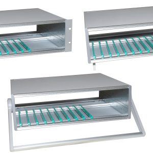
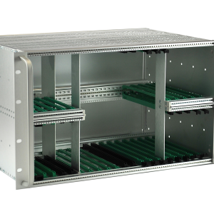
KM6-II Subrack Kit – Piece Parts
KM6-II subrack kits may be ordered by their constituent parts. This allows special configurations to be achieved including 4U and 7U subracks which can only be ordered from piece parts.
Download CatalogueSide Plates
KM6 side plates are punched on a 12mm pitch along their length to enable tie bars to be mounted to suit customer applications. On 300mm and deeper versions there is also a pattern of intermediate holes to permit the fixing of a chassis or support system. Identifications are stamped on the side plate to assist in tie bar location. Side plates are sold singly (i.e. 2 required for each subrack). The 4U x 360 and 7U x 420 versions can be assembled as 3U/6U + 2 x ½U or 3U/6U + 1U.
| Height | Depth (mm) | Thickness (mm) | Quantity | Order Code |
|---|---|---|---|---|
| 3U | 180 | 2 | 1 | 950-4002866 |
| 240 | 2 | 1 | 950-202787 | |
| 300 | 2 | 1 | 950-221911 | |
| 360 | 2 | 1 | 950-202790 | |
| 4U | 240 | 2.5 | 1 | 950-202618 |
| 360 | 2.5 | 1 | 950-202620 | |
| 6U | 180 | 2 | 1 | 950-4002820 |
| 240 | 2 | 1 | 950-202788 | |
| 300 | 2.5 | 1 | 950-221912 | |
| 360 | 2.5 | 1 | 950-202791 | |
| 420 | 2.5 | 1 | 950-202793 | |
| 7U | 420 | 2.5 | 1 | 950-259286 |
| 9U | 240 | 2.5 | 1 | 950-202789 |
| 300 | 2.5 | 1 | 950-224197 | |
| 360 | 2.5 | 1 | 950-202792 | |
| 420 | 2.5 | 1 | 950-202794 |
19” Rack Angles
| Height | Thickness (mm) | Quantity | Order Code (With Handle Holes) | Order Code (Without Handle Holes) |
|---|---|---|---|---|
| 3U | 2 | 1 | 950-232632 | 950-202783 |
| 4U | 2.5 | 1 | 950-4006100 | 950-202616 |
| 6U | 2 | 1 | 950-232633 | 950-202784 |
| 2.5 | 1 | 950-232635 | 950-202785 | |
| 7u | 2.5 | 1 | 950-259287 | |
| 9U | 2.5 | 1 | 950-202786 |
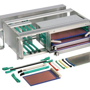
KM6-II Front Tie Bars
KM6-II front tie bars feature a screw fixing system using a unique dowel-screw arrangement which ensures accurate location and subrack rigidity. An additional slot is provided which, when fitted with a tapped strip, enables pcb and module guides to be secured using M2,5 x 5mm screws, thereby offering greater security and strength.
Provision is also made for the fitting of dust/EMC covers, without the need for additional seals, whilst still maintaining a high level of EMC screening.Normal front extrusions have slot identification printed along their length to aid guide location. Top versions also have a printed ident on the front face for panel location.
In addition to the normal front extrusion, there are other types:
PLAIN which has no guide location holes; this extrusion is included in EMC conversion kits and can also be used for just attaching additional panels (e.g. for rear socket mounting).
LIPLESS which has normal guide location holes but offers two facilities; if used as a height dividing extrusion, it is possible to use overall front panels; it will also fit within an EMC screen, permitting the recessing of cards.
These extrusions are supplied in lengths of 84HP and can easily be cut to length to suit other width requirements. These tie bars are not silk screen printed.
| Width | Description | Quantity | Order Code |
|---|---|---|---|
| 24HP | Tiebar – Top Front | 1 | 950-202796 |
| Tiebar – Bottom Front | 1 | 950-202795 | |
| 42HP | Tiebar – Top Front | 1 | 950-202736 |
| Tiebar – Bottom Front | 1 | 950-202735 | |
| 60HP | Tiebar – Top Front | 1 | 950-202743 |
| Tiebar – Bottom Front | 1 | 950-202742 | |
| 84HP | Tiebar – Top Front | 1 | 950-202644 |
| Tiebar – Bottom Front | 1 | 950-202643 | |
| Plain Front Tiebar | 1 | 950-221909 | |
| Lipless Front Tiebar | 1 | 950-233073 |
Top and Bottom Rear Tie Bars – Backplane Mounting
KM6-II rear tie bars adopt the same positive screw fixing method as the front ties bars. Once fitted with a tapped strip and the appropriate conductive or insulating spacer (to maintain the correct connector geometry), these tie bars act as supports for the top and bottom of a backplane. Top and bottom rear tie bars are supplied singly. Backplane tie bars can be converted to DIN 41612 by means of a connector mounting frame.
| Rear Tiebars | Backplane Mounting | Quantity | Order Code |
|---|---|---|---|
| 24HP | Top & Bottom | 1 | 950-202797 |
| 42HP | Top & Bottom | 1 | 950-202737 |
| 60HP | Top & Bottom | 1 | 950-202744 |
| 84HP | Top & Bottom | 1 | 950-201276 |
Mid Rear Tie Bars – Backplane Mounting
When fitted with tapped strips these tie bars are used as mid-rear backplane mountings. They can also be used to fit a 3U backplane into a 6U, or greater, subrack.
In order to maintain correct connector geometry it is necessary to fit a spacer, either conductive or insulating, between extrusion and motherboard/backplane. The centre rear tie bar comprises a two-part extrusion kit and a facility is provided for fitting a forward facing tapped strip if required. Backplane tie bars can be converted to DIN 41612 by means of a connector mounting frame.
| Width | Location | Quantity | Order Code |
|---|---|---|---|
| 24HP | Centre | 1 | 950-202798 |
| 42HP | Centre | 1 | 950-202738 |
| 60HP | Centre | 1 | 950-202745 |
| 84HP | Centre | 1 | 950-201277 |
Top and Bottom Rear Tie Bars – DIN 41612 Connector Mounting
KM6-II Top and bottom DIN 41612 connector mounting tie bars are pre-tapped with M2,5 holes on a 1HP pitch. These tie bars are printed with connector location idents to aid connector assembly, and are not handed.
| Rear Tiebars | DIN41612 Connector Mounting | Quantity | Order Code |
|---|---|---|---|
| 84HP | Top & Bottom | 1 | 950-229781 |
Mid Rear Tie Bars – DIN 41612 Connector Mounting
For DIN 41612 connector mounting the tie bar is pre-tapped M2.5 on a 1HP pitch. These tie bars are printed with connector location idents, but are not handed.
| Description | Location | Quantity | Order Code |
|---|---|---|---|
| 84HP | Top & Bottom | 1 | 950-229784 |
Tapped Strips
Tapped M2,5 holes on a pitch of 1HP, these strips are used for fixing front panels, backplanes, or as an option for chassis plates. As an alternative to tapped strips, a slide nut suitable for use in front tie bars only can be used where a small number of locations are required.
| Description | Quantity | Order Code |
|---|---|---|
| 24HP Tapped Strip | 1 | 950-202799 |
| 42HP Tapped Strip | 1 | 950-202739 |
| 60HP Tapped Strip | 1 | 950-202740 |
| 84HP Tapped Strip | 1 | 950-202001 |
| Slide Nut | 10 | 124-30499 |